
2 MIPS Architecture 32-bit RISC Processor 32 32-bit Registers, $0.$31Format: ADD rd, rs, rt Description: The contents of general register rs and the contents of general register rt are added to form a 32-bit result. The result is placed in general register rd. An overflow exception occurs if the two highest order carry-out bits differ (2’s-complement overflow).
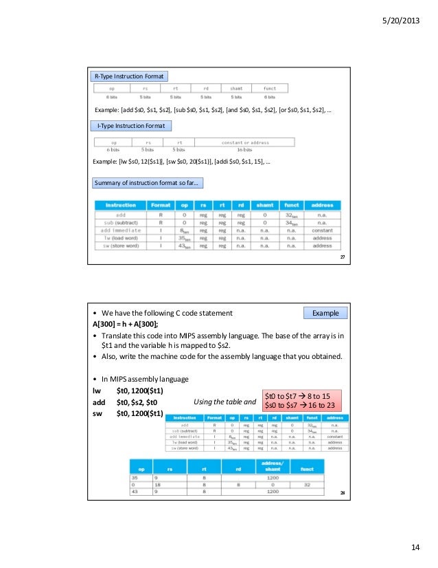
Recap of MIPS instruction set and formats. Introduce a new type of instruction format.R format - Uses three register operands Used by all arithmetic and logical instructions I format - Uses two register operands and an address/immediate value Used by load and store instructions Used by arithmetic and logical instructions with a constant J format - Contains a jump address Used by Jump instructions32-bit Instruction Formats R, I and J OP RS RT RD SHAMT FUNCT OP RS RT Address/Immediate OP Jump Address5 MIPS Instruction Set Only Load instruction can read an operand from memory Only Store instruction can write an operand to memory Typcial RISC calculations require Load(s) to get operands from memory into registers Calculations performed only on values in registers Store(s) to write result from register back to memory6 MIPS Addressing Modes Register - Uses value in register as operandExample $2 - Uses register 2 as operand Direct Address - Uses value stored in memory at given address Example Uses value stored at location 100 in memory as operand Register Indirect Address - Uses value in register as address of operand in memory Example ($3) - Uses value in register 3 as address of memory operand7 MIPS Addressing Modes Indexed Address - Adds address field and register value and uses this as address of operand in memory Example ($2) - Adds 100 to the value in register 2 and reads the operand from the resulting memory address Used for array X operations, the array index is normally in the register and the address field is the first location in the array8 MIPS Addressing Modes Immediate Addressing - Uses constant value contained in instruction Example addi $1,$2,4 - adds constant 4 to register 2 and stores result in register 1 Used for constants in programs PC relative - Address from instruction is added to the current value in the Program Counter Example J Jumps to address PC+4 Saves address bits in jump instructionsADD $1,$2,$3 Register 1 = Register 2 + Register 3 SUB $1,$2,$3 Register 1 = Register 2 - Register 3 AND $1,$2,$3 Register 1 = Register 2 AND Register 3 ADDI $1,$2,10 Register 1 = Register SLL $1, $2, 10 Register 1 = Register 2 shifted left 10 bitsLW $1,100 Register 1 = Contents of memory location 100 Used to load registers SW $1,100 Contents of memory location 100 = Register 1 Used to save registers LUI $1,100 Register 1 upper 16-bits = 100 Lower 16-bits are set to all 0’s Used to load a constant in the upper 16-bits Other constants in instructions are only 16-bits, so this instruction is used when a constant larger than 16-bits is required for the operationJ 100 Jumps to PC+100 JAL 100 Save PC in $31 and Jumps to PC+100 Used for subroutine calls JR $31 Jumps to address in register 31 Used for subroutine returnsBEQ $1, $2, 100 If register 1 equal to register 2 jump to PC+100 Used for Assembly Language If statements BNE $1, $2, 100 If register 1 not equal to register 2 jump to PC+100SLT $1,$2,$3 If register 2 is less than register 3 then register 1=1 else register 1=0 In an assembly language flag a “1” means true and a “0” means false Used in conjunction with Bxx instruction to implement any arithmetic comparision Required for more complex assembly language If statements14 MIPS Labels Instead of absolute memory addresses symbolic labels are used to indicate memory addresses in assembly language Assembly Language Programs are easier to modify and are easier to understand when labels are used Examples Variable X is stored a location 123 in memory - Use label X instead of 123 in programs. Location LOOP_TOP is address 250 in a program - Use label LOOP_TOP instead of jump address 250 in programsLW $2, B Register 2 = value of B LW $3, C Register 3 = value of C ADD $4, $2, $3 Register 4 = B+C SW $4, A A = B + CN. WORD 0 Like declaring an Integer, N, in a HLL Sets up N as a Label that points to a 32-bit data value Initial value is set to 0 LOOP: ADD $a0,$a0,$a1 Sets up LOOP as a Label that points to the Add instruction Can jump to LOOP (i.e. J LOOP)Assembler directives are commands for the assembler that do not generate machine instructions Assembler directives are also called pseudo ops Used to set up data and instruction areas.DATA The following lines are constant or data values.
It was my understanding that the reason you have to do the extra add instruction in the first solution, is actually because you cannot use a register as the offset. Assuming the base address of A is in register $s7 and the index (i) is in register $s1, I would have to do something along the lines of:What I'm confused about is my professor keeps saying that we can also do a lw instruction like this with 3 registers:Are both of these solutions correct? Or is my instructor incorrect? You can't use a register for the offset can you? I thought the offset had to be an immediate number.


 0 kommentar(er)
